I have noticed lots of people struggle with Xref CAD Linked files on Revit Servers.
This can be due to a number of things different folder location setups for each office, getting Consultant or Client required drawings, in which you need to link to your Revit model.
The easiest way for me to do this is by creating a new Revit Model called CADLinks or something similar.
Once this project is created Copy/Monitor Levels and Grids from your actual Project.
Then for floor, elevation, section views simply setup multiple views for each level for CAD Link as required then load them in, ensuring that the Links are in the correct positions with the Grids/Levels.
I normally make sure each link is then set to Foreground in the views. This will ensure that the CAD file overlays ontop of the floors or other model elements in the Project.
Once this is setup I activate worksharing and save the file to the Revit Server.
Then in my main Project file I load this file in onto it's own Workset and then for any views that require a Linked view for any reason you can just setup the View Settings with the Linked By View option and the correct CAD Linked view selected.
This way if other offices work on the Work in progress file there is no double of CAD Files, plus in your Master file there are no linked CAD files at all, which means no issues with CAD files being duplicated, or loaded into the distance.
Other issues I've encountered is bad CAD files or Objects in CAD files causing problems in project files, cleaning up the amount of links in your direct Project File.
This also speeds up reference loading since all the data for the linked views is stored in the Revit File Memory so it doesn't need to load 100's of references if your consultants have been using CAD or you are working with large civil datasets and drawings.
Monday, February 17, 2014
Tuesday, January 21, 2014
VEO 1.7.0 Update
Latest update of VEO is out, and damn the models are flying, they seem to really focus on making things faster and faster as well as improving on existing features as well as adding new ones.
Some great new features like measure and a status bar type UI element for allowing quick access to items and keeping track of your sync'ing and projects.
An important thing to note, for those outside North America we can access the Track module, this basically allows people out on site to scan barcodes and it will select various models, documents, or go to views based on the requirements back in the office for communication of issues and other problems.
Now this has been disabled by default however if you contact m-six support they will activate your account with this feature, if you are allowed to use it in your region at last check North America was unable to use this function.
Kudos to the Team, and looking forward to seeing more great enhancements to old features, speed and the addition of new features!!!
Tuesday, January 14, 2014
Conversion of Large Site Datasets for Visualisation
As an engineering firm with a very large Civil/Water team we do a lot of work with LiDAR surfaces and the like. These objects tend to be very top heavy although having them in their entirety in our rendering presentations certainly goes a long way to achieving not only a more realistic presentation for our clients, but as a interactive model for our engineers.
We use a number of platforms for our civil works and road designs due to our client requirements and simply some tools are better then others or some users prefer a tool and are good at their jobs, on any typical day in our office we have teams on 12D, Autodesk Civil3D, Bentley MX and/or Geopak.
Fortunately Autodesk acquired a tool a few years ago that imports all these tool sets called Civil View(Used to be Dynamite), built into 3DS Max Design as of 2014. Prior versions it was an addon bundled with the software.

Anyway as string/alignment designs (strings/alignments are a very important tool civil designer use to create roads, kerbs, drainage from a single polyline connected to an assembly, for Revit people think of sweeps that could auto cut/fill topography, as well as create the object) paths and surfaces can be complex sometimes the routines do not always play that nicely with bringing data in, other times it can simply be the size of the datasets. As a importation tool though for us it really does a great job to quickly create very large Civil Visualisations and Conceptual Options for stakeholders who are typically council, government related, and add visual enhancements like vehicles, road signage and that sort of thing.
String/feature lines in 3DS Max are only require if you want a line to layout objects like vehicles, traffic lights, signage etc.... otherwise they are not doing a huge amount for your file.
3ds Max is very stable with very large geometric datasets, and I've yet to create something for visualisation so unwieldy it was unable to handle the data, I should point out we use a GPU rendering tool and Max is our file container and manager of complex and large scene data, we don't use the rendering tools in it, only the animation and scene setups.
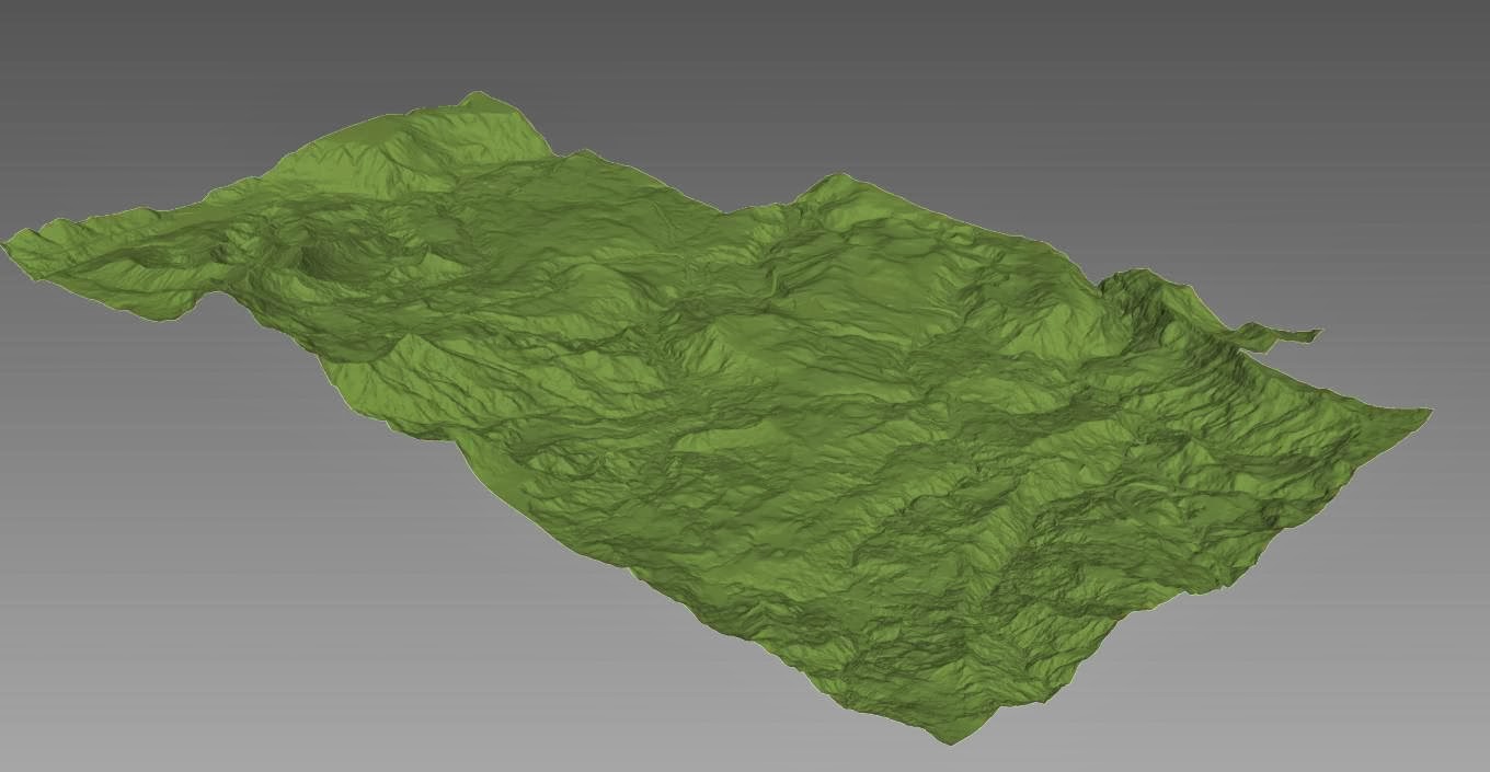
An example is the following of which I have been able to get the road designs and PAD's across but the software was unable to convert the main LiDAR surface from Civil3D.

In these case the surface wouldn't come across and the warnings in the export from Civil3D tell me that aswell. If you are guiding a Civil Engineer through this process make sure they tell you if there are any errors in the export to save any hassle with trying to figure out why Max isn't working, when it's not the issue.
As with any failures it's time to drop to the next attempt at importation and that's using landXML. LandXML is a pretty good format for exchanging data, however like IFC or DXF it creates large files that describe geometry and not design intent, most Civil programs work in similar fashion and the conversion is generally pretty good except for things like super elevations, assemblies and the like.
Anyway so I exported the LiDAR surface only, this generated a 1.5gig file. Now bringing this into 3ds Max takes a long time so make sure this is done as an overnight activity to not tie up resources. The final Max file was around 450mg and runs relatively very quick.

In this scenario I used the Export to Civil View for 3ds max tool, the other import tools in Max require the right settings from 12D or MX but there is no need for custom formats or exports like Civil3D. For 12D simply ask your civil designers for the main files they should be saved as ASCII format already, or depending on how they built their models you might want them to combine it all in a single export. 12D files handle large datasets for better then Civil3D without having to split files and create additional CAD management so in many cases our largest projects are done in 12D.
If you need complex scene animations, 4D, Road analysis or phasing your best to discuss with your Civil engineer what you are trying to achieve and if they are agreeable you can get them to quickly build a number of joined and split surfaces both existing and during/post construction to get the surfaces you need.
The end results really make a big difference on large civil projects with little time investment.

We use a number of platforms for our civil works and road designs due to our client requirements and simply some tools are better then others or some users prefer a tool and are good at their jobs, on any typical day in our office we have teams on 12D, Autodesk Civil3D, Bentley MX and/or Geopak.
Fortunately Autodesk acquired a tool a few years ago that imports all these tool sets called Civil View(Used to be Dynamite), built into 3DS Max Design as of 2014. Prior versions it was an addon bundled with the software.

Anyway as string/alignment designs (strings/alignments are a very important tool civil designer use to create roads, kerbs, drainage from a single polyline connected to an assembly, for Revit people think of sweeps that could auto cut/fill topography, as well as create the object) paths and surfaces can be complex sometimes the routines do not always play that nicely with bringing data in, other times it can simply be the size of the datasets. As a importation tool though for us it really does a great job to quickly create very large Civil Visualisations and Conceptual Options for stakeholders who are typically council, government related, and add visual enhancements like vehicles, road signage and that sort of thing.
String/feature lines in 3DS Max are only require if you want a line to layout objects like vehicles, traffic lights, signage etc.... otherwise they are not doing a huge amount for your file.
3ds Max is very stable with very large geometric datasets, and I've yet to create something for visualisation so unwieldy it was unable to handle the data, I should point out we use a GPU rendering tool and Max is our file container and manager of complex and large scene data, we don't use the rendering tools in it, only the animation and scene setups.
An example is the following of which I have been able to get the road designs and PAD's across but the software was unable to convert the main LiDAR surface from Civil3D.

In these case the surface wouldn't come across and the warnings in the export from Civil3D tell me that aswell. If you are guiding a Civil Engineer through this process make sure they tell you if there are any errors in the export to save any hassle with trying to figure out why Max isn't working, when it's not the issue.
As with any failures it's time to drop to the next attempt at importation and that's using landXML. LandXML is a pretty good format for exchanging data, however like IFC or DXF it creates large files that describe geometry and not design intent, most Civil programs work in similar fashion and the conversion is generally pretty good except for things like super elevations, assemblies and the like.
Anyway so I exported the LiDAR surface only, this generated a 1.5gig file. Now bringing this into 3ds Max takes a long time so make sure this is done as an overnight activity to not tie up resources. The final Max file was around 450mg and runs relatively very quick.
In this scenario I used the Export to Civil View for 3ds max tool, the other import tools in Max require the right settings from 12D or MX but there is no need for custom formats or exports like Civil3D. For 12D simply ask your civil designers for the main files they should be saved as ASCII format already, or depending on how they built their models you might want them to combine it all in a single export. 12D files handle large datasets for better then Civil3D without having to split files and create additional CAD management so in many cases our largest projects are done in 12D.
If you need complex scene animations, 4D, Road analysis or phasing your best to discuss with your Civil engineer what you are trying to achieve and if they are agreeable you can get them to quickly build a number of joined and split surfaces both existing and during/post construction to get the surfaces you need.
The end results really make a big difference on large civil projects with little time investment.

Sunday, January 5, 2014
Revit Server 2013 Model Corruption!!
Hey Guys
Happy New Year and I hope all enjoyed their holidays.
Here is a quick issue we have encountered and never knew about, if anyone is deleting models from Revit Server 2013 whilst any other users on ANY OTHER project on the server are synchronising within a couple of minutes of the Host server replicating the deletion changes with the Accelerators then the model they are working on will become corrupt.
So make sure any cleanup of the Revit Server 2013 is done outside of hours when people aren't working.
PS Revit Server 2014 does not seem to have this issue.
Monday, December 16, 2013
Correct Annotation Orientation of Sloped Details in Revit.
Ok RTC talks for both AUS and USA are in, for those who don't know if you log in to the RTCAUS submit speaker tool you can actually see if your talk has been accepted or not for RTCAUS only.
However not sure how official this is until the actual emails of confirmation go out, but check anyway!!
A user had an interesting issue the other day, I have replicated a simple version for example.
Basically he wanted an angled detail showing the true length of the member, here is a simple layout below of the project.

Now you can see in the Elevation he has gone ahead and drawn a Detail Section View as you cannot draw sections on angles.
Now when the view generated it did two interesting things, first the changed from Vertical layout to Horizontal, and any attempts to rotate the crop box fail, you can rotate it successfully to any but 90 degrees.
However we were able to place it on a sheet and use the rotate sheet view as seen below.

Once we applied dimensions they weren't correct orientation nor was the detail view title as you can see.
So with this in mind we thought we would try to create an assembly view, one thing not commonly know about assemblies if you can modify the orientation to generate views automatically based on the Origin Point.
So we selected the object and made the frame into an assembly, then we edit the assembly, you can see the dot and we just need to move it to the correct height and then rotate the point to match the angle of the framing you might need to set your workplanes for this.
Your point should reflect something like the following.
 Once you have done this you should see the framing plan similar to before only this time you can actually rotate the crop boxt to 90 degrees and then place it on the sheet correctly.
Placing this on a sheet then rotating did not fix the issue, so you must rotate the cropbox.
You will get correct orientation of titles, dimensions and tags.
Obviously a downfall is this only works with items that can work with assemblies.

Alright I'm off on holidays with the family, so safe travels and merry xmas, happy new year and hopefully I will kick off with some of the other things I am doing with Dynamo and the API.
However not sure how official this is until the actual emails of confirmation go out, but check anyway!!
A user had an interesting issue the other day, I have replicated a simple version for example.
Basically he wanted an angled detail showing the true length of the member, here is a simple layout below of the project.

Now you can see in the Elevation he has gone ahead and drawn a Detail Section View as you cannot draw sections on angles.
Now when the view generated it did two interesting things, first the changed from Vertical layout to Horizontal, and any attempts to rotate the crop box fail, you can rotate it successfully to any but 90 degrees.
However we were able to place it on a sheet and use the rotate sheet view as seen below.

Once we applied dimensions they weren't correct orientation nor was the detail view title as you can see.
So with this in mind we thought we would try to create an assembly view, one thing not commonly know about assemblies if you can modify the orientation to generate views automatically based on the Origin Point.
So we selected the object and made the frame into an assembly, then we edit the assembly, you can see the dot and we just need to move it to the correct height and then rotate the point to match the angle of the framing you might need to set your workplanes for this.
Your point should reflect something like the following.

Once the location is set you can then generate your views, anytime you make a plan detail view always make an elevation or section view, this is because by default the plan views ends up cutting the middle of the assembly and you need to move the section marker in the assembly elevation view above all the objects to see all the members.
Placing this on a sheet then rotating did not fix the issue, so you must rotate the cropbox.
You will get correct orientation of titles, dimensions and tags.
Obviously a downfall is this only works with items that can work with assemblies.

Alright I'm off on holidays with the family, so safe travels and merry xmas, happy new year and hopefully I will kick off with some of the other things I am doing with Dynamo and the API.
Wednesday, December 11, 2013
Amazon EC2 Services & VEO
So one project I am involved with at the moment is a test bed Integrating IBM Maximo and VEO together.
We have a project recently completed that required a Combination of Plant3D, Civil3D and Revit.
We managed to get the data into VEO directly from Plant and Civil using a cool trick that the dev team gave me. This involved putting the VEO AutoCAD plugin files into our AutoCAD verticals and running the exporter.
We are using a test environment that needs to be accessed by multiple parties in Australia, Philippines and the US so we thought the best way forward would be to setup a Amazon service account to allow access.
We are using the paid version as we use a number of services, however there is a free startup version that last for 12 months fulltime and limited compute/data for those who want access to their own cloud PC on the go.
There is alot of hype of cloud and what Amazon actually provides so this will go through what a setup is, what you actually get with Amazon and how it's charged.
Amazon EC2 service is the ability to create virtual machines that you can create online through the Amazon web app, then access via Remote Desktop(RDP).
The solution is nice is you can start and stop the instance anytime you want, and you are only charged for the compute time the actual VM is running, for anyone using VMware or Citrix this should be common stuff.
For anyone interested in trying VM technology Virtualbox is an awesome free software that allows you to make many virtual machines, if you have spare windows, licenses or want to trail Linux it works perfectly, and great testing environment for all sorts of things. I primarily use it for web programming testing environments and beta software.
So anyway if you go to AWS you can see the sign up for free or create an account.

Once this done you can log into the management console with your user name and password.
There are a whole ton of services you can activate and use on the fly but I am only interested in the EC2 service at this point in time.

Once inside you can see the dashboard and there is an option to create an "Instance"(instance is a single Virtual Machine). This will then allow you to set the specs for how much CPU, RAM and space you want, this is all tied to the cost structure, so don't go latest and greatest unless you really need it!! This stuff is like a teenager with a brand new iphone and no lockage on internet use, you can very quickly rack up large dollars if your not careful and read everything :)
Your Dashboard looks something like this.

On the left hand side I can then click on instances and see all my virtual machines I have created if I right click on an instance I will get options to start/stop the instance and all sorts of stats the key is really the start stop, we always stop our session when finished if your running web or services you need live then fair enough, but for our testbed with our specialist all adding various parts to our system we only have it on when someone is accessing the system.

Once started there is some bootup time, and some status checks need to be performed, once everything checks ok and green lights up you can connect to your instance.
You can either download the RDP or type the details in your Remote Desktop login.
I prefer to download each time as our IP address changes and that linked to the login also machines on domains might not recognise the login name.
Once logged into your operating system you can work as per normal.
Obviously depending where you are in relation to your can cause some lag but I was able to work on a US West Coast server from Philippines with little issue.
I'll follow up on how Maximo and VEO integration is going later, but suffice to say so far we are have some favourable results and a workflow for making this reality.
Tuesday, December 10, 2013
Introduction & VEO
Well after many years of thinking about it I thought I would finally kick off my first blog.
I have decided I need a place to keep track of all my bits & pieces I solve as I work on various things and thought this would be the place to do it.
So an issue many people have with VEO when starting out is that any sort of photo realistic materials can't be modified in terms of selecting new images.
As a result the non-rendered images when we are trying to achieve things like Blockwork or CMU aren't achievable at this point in time.
Here is a way to swap out materials with ones you want.
Disclaimers: This hack won't render, nor is it shareable unless you copy the images onto someone else's cached version of VEO.
Anyway back to the hack.
In the location where your VEO_Cache folder resides(by default this in your documents) there is a folder called TextureCache.
The Cache contains any images from projects that have applied materials that you have viewed in VEO.

Each image is stamped with a long ID and stored as a jpg.
This file name is fixed in the VEO cloud or render service so you can easily put the cache on any material on any system and you will get the result.
Apply a particular style in VEO and then simply find the matching image in the texturecache folder.
All you need to do is get any image you wish and rename to the identical name of the image you are replacing.

When you open VEO and reload the project you should see the updated image on any objects assigned with that material.

The images are by default 512 pixels so simply adjust to get your scaling and tiling correct.
Subscribe to:
Posts (Atom)