As an engineering firm with a very large Civil/Water team we do a lot of work with LiDAR surfaces and the like. These objects tend to be very top heavy although having them in their entirety in our rendering presentations certainly goes a long way to achieving not only a more realistic presentation for our clients, but as a interactive model for our engineers.
We use a number of platforms for our civil works and road designs due to our client requirements and simply some tools are better then others or some users prefer a tool and are good at their jobs, on any typical day in our office we have teams on 12D, Autodesk Civil3D, Bentley MX and/or Geopak.
Fortunately Autodesk acquired a tool a few years ago that imports all these tool sets called Civil View(Used to be Dynamite), built into 3DS Max Design as of 2014. Prior versions it was an addon bundled with the software.
Anyway as string/alignment designs (strings/alignments are a very important tool civil designer use to create roads, kerbs, drainage from a single polyline connected to an assembly, for Revit people think of sweeps that could auto cut/fill topography, as well as create the object) paths and surfaces can be complex sometimes the routines do not always play that nicely with bringing data in, other times it can simply be the size of the datasets. As a importation tool though for us it really does a great job to quickly create very large Civil Visualisations and Conceptual Options for stakeholders who are typically council, government related, and add visual enhancements like vehicles, road signage and that sort of thing.
String/feature lines in 3DS Max are only require if you want a line to layout objects like vehicles, traffic lights, signage etc.... otherwise they are not doing a huge amount for your file.
3ds Max is very stable with very large geometric datasets, and I've yet to create something for visualisation so unwieldy it was unable to handle the data, I should point out we use a GPU rendering tool and Max is our file container and manager of complex and large scene data, we don't use the rendering tools in it, only the animation and scene setups.
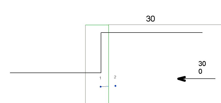
An example is the following of which I have been able to get the road designs and PAD's across but the software was unable to convert the main LiDAR surface from Civil3D.
In these case the surface wouldn't come across and the warnings in the export from Civil3D tell me that aswell. If you are guiding a Civil Engineer through this process make sure they tell you if there are any errors in the export to save any hassle with trying to figure out why Max isn't working, when it's not the issue.
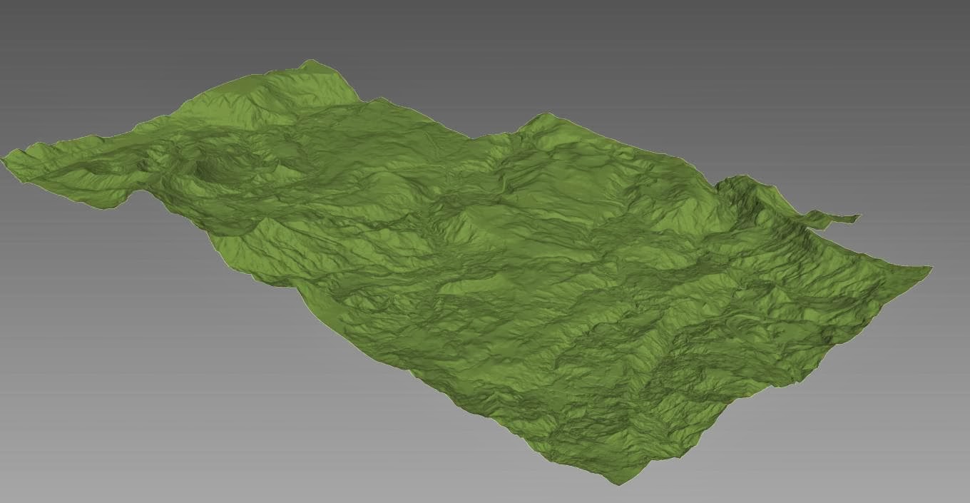
As with any failures it's time to drop to the next attempt at importation and that's using landXML. LandXML is a pretty good format for exchanging data, however like IFC or DXF it creates large files that describe geometry and not design intent, most Civil programs work in similar fashion and the conversion is generally pretty good except for things like super elevations, assemblies and the like.
Anyway so I exported the LiDAR surface only, this generated a 1.5gig file. Now bringing this into 3ds Max takes a long time so make sure this is done as an overnight activity to not tie up resources. The final Max file was around 450mg and runs relatively very quick.
In this scenario I used the Export to Civil View for 3ds max tool, the other import tools in Max require the right settings from 12D or MX but there is no need for custom formats or exports like Civil3D. For 12D simply ask your civil designers for the main files they should be saved as ASCII format already, or depending on how they built their models you might want them to combine it all in a single export. 12D files handle large datasets for better then Civil3D without having to split files and create additional CAD management so in many cases our largest projects are done in 12D.
If you need complex scene animations, 4D, Road analysis or phasing your best to discuss with your Civil engineer what you are trying to achieve and if they are agreeable you can get them to quickly build a number of joined and split surfaces both existing and during/post construction to get the surfaces you need.
The end results really make a big difference on large civil projects with little time investment.